A Study of Pinhole Photography
Please note that since this article was first written and researched, I have discovered a number of discrepancies. In order to keep this article intact, I have created an erratum page.
 In order to see,
we have to detect light rays which are either emitted or
reflected from the surface of objects. These light rays fan out
in all directions and mix with light rays from other sources (see
figure 1) or parts of the object being viewed. Without a way of
filtering and sorting these light rays, it would be like looking
through frosted glass where only areas of light and dark or
patches of colour can be detected. Our eyes and most optical
devices in common use today, depend on lenses to focus and
collect rays of light to form an image.
In order to see,
we have to detect light rays which are either emitted or
reflected from the surface of objects. These light rays fan out
in all directions and mix with light rays from other sources (see
figure 1) or parts of the object being viewed. Without a way of
filtering and sorting these light rays, it would be like looking
through frosted glass where only areas of light and dark or
patches of colour can be detected. Our eyes and most optical
devices in common use today, depend on lenses to focus and
collect rays of light to form an image.
Light rays are individual waves of
electromagnetic radiation like radio waves except at a much
higher frequency. FM radio is around 100MHz or oscillations per
second where as visible light has an average frequency of 1,000,000,000MHz.
(10 million times higher).
Waves, have three basic properties which allow
us to manipulate them –
Reflection where light rays bounce off a
surface rather than passing through or being absorbed.
Refraction where light rays passing across
the boundary between two materials e.g. from air to glass
is bent.
Diffraction where light rays are bent as
the pass over an edge.
Lenses use refraction to bend the light rays and effectively
separate and collect them (see figure 2). As the light rays enter
and leave the lens, they are bent by a fixed amount referred to
as the refractive index. All the rays leaving point "A"
and hitting the surface of the lens are focused and reconstituted
to form point " ".
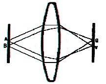 |
| Figure 2 - Light Rays being bent by a lens |
There is however a much simpler way in which to filter the light rays
and produce an image. The technique is called pinhole and basically uses a small hole to untangle the light rays and form an image (see figure 3)
 |
Figure 3 - Comparison of Image Forming Devices
Left No image forming device, Centre A Pinhole, Right A Lens |
The hole in a pinhole device only allows a
small number of rays that are shining directly at it to pass
through. The resulting image is made up of small dots which
correspond to the shape and size of the pinhole. The smaller the
pinhole, the better the resolution or clarity of the image
however this raises other problems. Pinholes basically act as a
filter so as the hole gets smaller, less light is allowed to
enter and the image becomes very dim and requires long exposure
times.
Another more significant problem with small apertures is
caused by diffraction. As the light passes through the hole, it
is bent, making it fan slightly. The resulting image forming dot
when looked at closely, consists of a pattern of light and dark
concentric rings around a dark central point (known as an Airy
disc). As the pinhole gets smaller, this effect becomes more
pronounced and effectively starts to make the image forming dots
larger. There is therefore an optimum size for a pinhole which
gives the smallest image-forming dot.
Although pinholes have limitations in terms of resolution and
image intensity, they have the major benefit of not needing to be
focused. Everything in the field of view is in focus whatever its
distance from the pinhole. This makes them useful for a large
number of other applications like glasses and scientific cameras
for imaging objects that emit other forms of radiation.
While the science of the pinhole appears to be
quite complex, pinholes are probably the oldest and simplest
optical devices known to man. A Chinese document from about 4000BC
makes an oblique reference to pinholes however Aristotle was the
first western philosopher to describe the phenomenon and asked:
#6: Why is it that when the sun passes through
quadrilaterals, as for instance in wickerwork, it does not produce figures rectangular in shape but
circular.
This question became known as Aristotle’s question and was not
solved until 1521. Pinholes were most commonly used as part of
time keeping devices or sundials called gnomon. The gnomon was a
stick or column with a hole at the top. The sun casts a shadow of
the stick on the ground which is topped by a bright spot which is
an image of the sun projected through the hole. As the year
progressed, the spot would also move towards or away from the
column. By measuring this distance, astronomers were able to mark
the passing of the seasons and years. Cathedrals being dark
buildings were ideal places for these clocks and from the late 15th
century many cathedrals had pinholes fitted in the roof and
"noon" marks placed on the floor. Indeed the papal
astronomers were able to persuade Pope Gregory to change the
calendar in 1580 when they showed using one of these devices,
that the spring solstice was 10 days earlier than it should have
been.
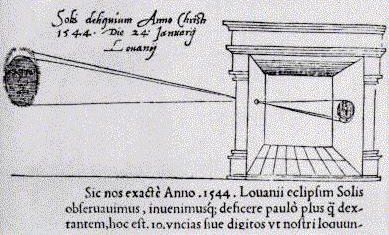 |
| Figure 4 - Gemma Frisius's Camera |
Scientists used pinholes to produce small beams
of light which could be shone onto prisms and lenses for optical
experiments. No doubt they were used for many other experiments
and observations however the first documented observation of the
solar eclipse using a pinhole to project an image on the wall of
a darkened room was in 1544. This same astronomer, Gemma Frisius,
used the same apparatus to observe the sun and was probably the
first person to see sunspots. Many artists started to use Frisius’s
technique to project images onto the canvas which were then
traced and painted over. The adoption of lenses made the pinhole
images brighter, clearer and easier to work with. By the 1570’s
the scientific term Camera Obscura (literally translated as dark
room) was in general use and used to describe a tent, box or
darkened room with a lens aperture used by artists as an aid to
draw the landscape. Leonardo da Vinci used pinholes for his
experiments on perspective among other things and wrote about
their image forming properties in his Codex Atlanticus.
The development of photography in the early 19th
century is inextricably linked to pinholes and the Camera Obscura.
While most early cameras used lenses, a number are known to have
been made with just a pinhole as the image forming device. In
fact, the English scientist Sir David Brewster coined the term
"pinhole" during this period. The soft focus effect a
pinhole camera produces became extremely popular during the 1880s
because of the "impressionist" art movement. However,
the Great War, lens technology and public expectation for sharp
images meant that by the 1930s pinhole techniques were all but
forgotten about.
Pinhole cameras still remain the simplest kind
of photographic equipment to make and experiment with however,
and the resulting images have a character and charm of their own.
They consist of a light tight box with some photographic material
and a small hole (the pinhole) that can be covered up (a simple
shutter). Cameras have been made from paper bags, cereal boxes,
eggshells and even holes in walls. The pinhole is the most
important part of this kind of camera and it has two important
features - size & thickness. The optimum size of a pinhole is
dependent on the colour of light you are working with and the
focal length (distance from the pinhole to the film medium). Lord
Rayleigh is credited as being the first person to develop a
formula that modelled this complex relationship in 1889. Further
developments in wave theory and Fresnel Lenses has shown that
pinholes are in fact simple zone plates and are governed by the
following formula –
 or
or 
where d is the diameter of the pinhole, f
is the focal length and l
is the wavelength of the light being used.
For visible light, the average wavelength is 0.56 mm and for a 35mm
camera, f =0.035m and therefore the pinhole diameter
should be 0.28mm. The only other bit of maths required for
pinhole cameras is the calculation of the effective aperture and
the exposure compensation.
In order to create an image on photographic
material, a certain amount of light must fall on it. The amount
of light that is required for an ideal exposure depends on the
film material and is measured in terms of its speed rating i.e. a
faster film needs less light and vice versa. The shutter and
aperture controls restrict the amount of light reaching the film
like a tap. A fully opened tap will fill a cup in less time than
a partially open tap. There is therefore a range of tap openings
and time settings that will result in a full cup (and many more
that will result in a partially full or overflowing cup. The
pinhole camera has a fixed aperture (the tap is fixed open in one
position) so in order to provide the right amount of light for
the film, we need to adjust the amount of time we let light enter
the hole.
An exposure meter is normally used to calculate
the ideal settings for the shutter and aperture for a given
subject’s lighting and film speed. In order to use the
meter, we need to know the effective aperture of the pinhole.
This is simply the focal length divided by the diameter of the
hole i.e. 0.035/0.00028 = 125. This aperture is much smaller than
most meters can handle (normally limits are f/32 or f/64) however
we can use the meter to give a reading at f/16 and convert the
exposure time by multiplying it by a factor which is calculated
as follows –
where F is the aperture or f-stop. Using our
example, the exposure factor would be 60 i.e. we would multiply
the exposure time given by the meter at f/16 by 60. One final
problem with exposure is reciprocity failure of the film or light
sensitive material. Basically, the photographic medium loses
sensitivity as the exposure times get longer and therefore
requires more light, i.e. the film gets slower. Some
manufacturers print data sheets that give exposure information
and which identify when reciprocity starts to have an effect as
well as a guide to compensation. If this information is not
available then exposure bracketing is recommended for exposures
over 1 minute.
Construction of the pinholes is relatively
simple although care needs to be taken. The material used should
be as thin as possible prevent vignetting and minimise
diffraction so sheet metal or foil lids are ideal (I used a milk
bottle top to experiment with). Ensure the material is flat and
placed on a cutting mat or some stiff cardboard gently pierce the
centre of the sheet with a fine pin or needle. Ensure that the
tool is kept perpendicular to the material and use a twisting
motion (This will ensure that a round hole is created). When the
needle breaks through, turn the sheet over and reverse the
process. Using this process, I was able to create a hole 0.15mm
in diameter in a milk bottle top. Bigger holes can be created in
a similar way however stiffer material may have to be used to
prevent distortion and bending.
An alternative technique is to use a centre
punch to mark the centre of the material. Using fine emery paper,
sand away the bump created on the reverse side until a hole
appears. The edges of the hole can be tidied with a pin or nail
to make sure that they are round. One benefit of this process is
that the edge of the hole is kept quite thin where it has been
stretched by the punch.
Once the pinhole has been manufactured, its
diameter needs to be checked. For larger holes, this is not so
much of a problem but holes in the order of tenths of millimetres
cannot be measured accurately with a ruler! The simplest method
is to use an enlarger or projector to project an image of the
pinhole onto a screen and measure the size of the image. Replace
the pinhole with a hole of a known size and measure the image
this creates. The magnification of the enlarger can be calculated
from the increase in size of the known hole and then the pinhole
size can be calculated using the magnification factor.
Alternatively, the hole size can be calculated from the exposure
settings which produced a well exposed print using the formulas
already discussed.
 Making the camera itself is
quite simple, as all that is required is a light tight container
big enough to hold the photographic material you want to use. For
example, a biscuit tin can be easily converted into a camera by
painting the inside black, making a hole in the lid (either a
pinhole or a hole big enough to mount the pin hole behind) and
then mounting the photographic material in the base. A piece of
insulating tape can be used to cover the pinhole until you are
ready to make the exposure. A beer or drinks can is another
household product that can be pressed into use as a camera. By
carefully cutting the top of the can and rubbing the edges down
with emery paper, a light tight lid can be made by blocking the
ring pull and creating a sleeve around the inside with card. A
hole pierced in the middle of the body will act as a pinhole (remove
all rough edges) and a shutter can be improvised with black tape.
The photographic material can be either curled around the body of
the can or held flat on an improvised holder. These cameras are
so simple to make that you could go on a shoot with a six pack!
Making the camera itself is
quite simple, as all that is required is a light tight container
big enough to hold the photographic material you want to use. For
example, a biscuit tin can be easily converted into a camera by
painting the inside black, making a hole in the lid (either a
pinhole or a hole big enough to mount the pin hole behind) and
then mounting the photographic material in the base. A piece of
insulating tape can be used to cover the pinhole until you are
ready to make the exposure. A beer or drinks can is another
household product that can be pressed into use as a camera. By
carefully cutting the top of the can and rubbing the edges down
with emery paper, a light tight lid can be made by blocking the
ring pull and creating a sleeve around the inside with card. A
hole pierced in the middle of the body will act as a pinhole (remove
all rough edges) and a shutter can be improvised with black tape.
The photographic material can be either curled around the body of
the can or held flat on an improvised holder. These cameras are
so simple to make that you could go on a shoot with a six pack!
When designing or choosing objects to be used
as pinhole cameras, there is one further property that needs to
be taken into account. The light shining through a pinhole
produces a cone of line with an angle of 125 degrees at its apex.
For every inch from the pinhole the circular image produced
increases in diameter by 3.5 inches (see figure 6). There is
therefore a minimum distance from the pinhole to place a piece of
film to ensure that the image covers the whole area and does not
start to vignette or produce a circular image. The smallest image
forming circle that can be used is the same as the measurement of
the diagonal e.g. a sheet of paper 10"x 8" has a
diagonal of 12¾ inches, therefore the image forming circle has
to be a minimum of 12¾ inches diameter. The minimum distance
from the pinhole would therefore be 3¾ inches. One further point
to remember is that the light intensity falls of towards the
edges of the cone which makes choosing an exposure value
difficult. One way round this is to use a larger focal length i.e.
distance from hole to camera so that the image is formed from the
central area of the cone where the light intensity is more
constant. Alternatively, using more than one pinhole and making
sure that the cones overlap slightly will ensure that large
images at short focal lengths can be created.
 |
| Figure 6 - Pinhole Image Forming Cone |
Modifying an existing camera by removing the
lens and replacing it with a pinhole avoids these issues and has
the added benefit of already having a shutter and film transport
mechanism. Cameras with detachable lenses like SLRs are the best
for this as they can be modified without causing permanent damage.
Most cameras with detachable lenses have body caps which cover
the hole in the body when a lens is not attached. These are
normally made from quite thick plastic and so are impractical to
have a pinhole drilled in them. They can however be used to hold/support
a pinhole by drilling a 15mm hole in the centre and sticking a
pinhole made from sheet metal behind it.
 |
| Figure 7 - Canon EOS500 fitted with PinHole |
Photographs 2 & 4 were taken with the
camera in figure 7 and photographs 1 & 3 were shot of the
same scene using a lens with the same focal length as a
comparison. The pinhole produced remarkable clear images which
are bright and clear even though the pinhole I used was half the
optimum size. These pinhole images also highlight one drawback
which is that they cannot be enlarged greatly without producing a
grainy effect or exaggerating the soft focus. It is always best
therefore to take pinhole images at the size you want to use them
to maximise the resolution and clarity.
Pinholes can be used in other applications for
example in an enlarger. Photographs 6 & 7 were printed by
myself on the college enlargers using a pinhole with 0.4mm
diameter instead of a normal lens. Photograph 5 is a commercial
print for reference. The prints I made are a bit light and would
have been better on a harder grade of paper however they proved
that the process is possible and apart from problems with long
exposure times caused by the low light levels, it was very simple
to do.
Pinholes are not the only non-lens image
forming device that can be used. A zone plate (basically a
Fresnell Lens) can be easily constructed to replace the pinhole.
As the zone plates have to be very small, they tend to be
photographically reduced from templates like figure 8. Slits can
also be used and they can create some interesting distortions.
The focal length in the horizontal plane is different from that
of the vertical plane therefore stretching the image.
While pinhole cameras have been relegated from
the premier league of photographer’s equipment, they are
still in common use in scientific applications where lenses are
impractical. Gamma and X-ray imaging of the sun and the solar
system is only possible with pinhole as lenses absorb this kind
of radiation. These cameras use multiple pinhole optics known as
coded-aperture imaging and require powerful computers to decode
the images. Another application is in the nuclear industry when
pinhole cameras are used during experiments in nuclear fusion to
photograph the explosions.
 |
 |
| Figure 8 - Zone Plate Template |
Figure 9 - Slit Camera |
Pinhole and other non-lens imaging is an under
rated technique which is a shame as it has many things to offer
the photographer. Apart from their ease of construction,
virtually infinite depth of field and non-distorted imaging, they
provide a degree of experimentation and creativity which can not
be easily achieved with a lens based equivalent. Pinhole cameras
are ideal for teaching the basic principles of photography while
offering the more experienced photographer an unusual view of the
world.
Erratum
End Notes
Problems XV, Aristotle circa 400BC extract taken from Pinhole Photography 2nd Edition, Eric Renner
A Fresnel Lens or Zone Plate uses diffraction rather than refraction to bend the light rays. The lenses are typically flat with a pattern of ridges or lines in concentric circles. These lenses are thin, light and simple to manufacture and are used in applications where optical quality is generally not so important.
Successful Pinhole Photography D. Ambrosini and G. Schirripa Spagnolo, American Journal of Physics, March 1997, P256
Basic formula and principle taken from "Basic Pinhole Photography" Mark Hahn,
http://www.geocities.com/markhahn2000/pinhole_concepts.html 26/04/2000
Bibliography
Pinhole Photography 2nd Edition, Eric Renner, Butterworth Heinemann, 2000
Master Photography, Mike Busselle, Micheal Beazley Publishers Ltd., 1979
Pinhole Photography, John Grepstad, http://home.sol.no/~gjon/pinhole.com 28/03/2000
Basic Pinhole Photography, Mark Hahn, http://www.geocities.com/markhahn2000/pinhole_concepts.html 26/04/2000
Handmade Photographic Images, George L Smith, http://members.home.net/hmpi/pinhole/articles/makepinhole/makepinhole.htm 19/04/00
The Pinhole Camera, Matt Young, http://www.pinhole.com/resources/articles/young/index.html 19/04/2000
Making a Pinhole, Larry Bullis, http://www.pinhole.com/resources/makingholes.html 19/04/2000
The Double Slit, Patton, http://www.stanford.edu/~cpatton/ds.html 19/04/2000
Successful Pinhole Photography, D. Ambrosini and G. Schirripa Spagnolo, American Journal of Physics, March 1997, P256
Photo Credits
Figure 1 - Rays of Light Mixing © Bob Manekshaw
Figure 2 - Light Rays being bent by a lens © Bob Manekshaw
Figure 3 - Comparison of Image Forming Devices © Mike Busselle, Master Photography, p42
Figure 4 - Gemma Frisius's Camera © John Grepstad, http://home.sol.no/~gjon/pinhole.com
Figure 5 - Can Camera © John Grepstad, http://home.sol.no/~gjon/pinhole.com
Figure 6 - Pinhole Image Forming Cone © Bob Manekshaw
Figure 7 - Canon EOS500 fitted with PinHole © Bob Manekshaw
Figure 8 - Zone Plate Template © C Patton, http://www.stanford.edu/~cpatton/ds.html
Figure 9 - Slit Camera © C Patton, http://www.stanford.edu/~cpatton/ds.html
Photographs 1-7 © Bob Manekshaw