The Art of Stereo Photography
 The portrayal of depth in paintings and later in
photography has been a long quest for artists. It was not until
the early 15th century during the Renaissance period
that the techniques for showing perspective were first
demonstrated by the Italian architect Bruneselleschi. Leonardo da
Vinci in his "Trattato della Pittura", refers to a
"perspective frame" as his method of studying
diminishing perspective. The artist would look through the
eyepiece and see an image of the subject on the paper clipped to
the glass plate. The artist would then draw around the visible
outline on the paper to produce a drawing with perspective.
Leonardo also developed another system called aerial perspective
whereby the misty atmosphere blurs and changes the colours of the
landscape as it dissolves into the distance.
The portrayal of depth in paintings and later in
photography has been a long quest for artists. It was not until
the early 15th century during the Renaissance period
that the techniques for showing perspective were first
demonstrated by the Italian architect Bruneselleschi. Leonardo da
Vinci in his "Trattato della Pittura", refers to a
"perspective frame" as his method of studying
diminishing perspective. The artist would look through the
eyepiece and see an image of the subject on the paper clipped to
the glass plate. The artist would then draw around the visible
outline on the paper to produce a drawing with perspective.
Leonardo also developed another system called aerial perspective
whereby the misty atmosphere blurs and changes the colours of the
landscape as it dissolves into the distance.
Perspective in drawing and painting remained the only way of
providing the illusion of depth on a 2-D canvas until 1838 when
Sir George Wheatstone gave a lecture on binocular vision.
Wheatstone made a device called a "Reflecting Mirror
Stereoscope" with which to view his 3-D drawings (the
original device has been preserved in the Science Museum).
However, it took a further twelve years before Scotsman Sir David
Brewster invented the first practical photographic device called
a "Lenticular Stereoscope". Brewster presented Queen
Victoria with a stereoscope in 1851 at the Great Exhibition in
the Crystal Palace which helped to popularise the medium.
Many photographic companies developed to market stereo
photocards (stereograms) and stereoscopes. Photographers were
sent across the world to record famous sights and events in
stereo in order to quench Victorian society’s thirst for
knowledge. "See the world from your parlour!",
is just one of the many advertising slogans from the time which
seems to sum up the power of the new media. It has to be
remembered that most people’s view of the world at that time
came from paintings, wood prints and drawings and so the
excitement of seeing real images in three dimensions must have
been tremendous. The medium was so popular that most photographs
taken in the Victorian period were stereograms although we now
tend to see them as single images. A good example of this is the
famous photograph of Isambard Kingdom Brunel in front of the
launching chain of the steamship "The Great Eastern" by
Robert Howlett which we typically see as a single shot but which
was intended to be viewed as a stereogram. The stereoscopes
themselves became very complicated and designs varied
tremendously from the single card viewer to a machine that could
store and view fifty or more stereograms.
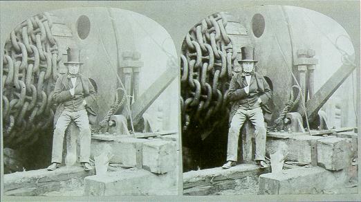 Figure 2 - Isambard
Kingdom Brunel
Figure 2 - Isambard
Kingdom Brunel
 Stereograms and stereo photography started to
lose public popularity during the early part of the twentieth
century as cameras and photography became simpler and cheaper.
George Eastman began the trend for consumer photography with his
KODAK cameras in the early 1900s and the development of 35mm
cameras in the 1920s marked the beginning of the end for the
stereo technique. 3-D photography proved to be to complicated and
expensive for the average `snapper’ and required a
special viewing device. 3-D pictures could not be enlarged, put
in a frame, album or hung on a wall which further reduced their
flexibility. A number of manufacturers did try and make the
technique simpler by producing stereo cameras like the Kodak
Stereo Realist but the ease and simplicity of single 2-D images
meant that the technique remained the realm of the keen amateur
and professional photographer.
Stereograms and stereo photography started to
lose public popularity during the early part of the twentieth
century as cameras and photography became simpler and cheaper.
George Eastman began the trend for consumer photography with his
KODAK cameras in the early 1900s and the development of 35mm
cameras in the 1920s marked the beginning of the end for the
stereo technique. 3-D photography proved to be to complicated and
expensive for the average `snapper’ and required a
special viewing device. 3-D pictures could not be enlarged, put
in a frame, album or hung on a wall which further reduced their
flexibility. A number of manufacturers did try and make the
technique simpler by producing stereo cameras like the Kodak
Stereo Realist but the ease and simplicity of single 2-D images
meant that the technique remained the realm of the keen amateur
and professional photographer.
 Having said all this, a number of attempts have
been made to revive to revive the format and new technologies
developed to simplify the viewing and taking of these pictures.
During the twentieth century, stereo photography became more
commercialised and a small number of companies emerged who
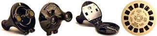
specialised in producing stereo images and viewers. The most well
known of these is "View-Master", an American company
founded in the late 1930s. The View-Master systems uses 7 pairs
of photographs (slides) mounted around the circumference of a
90mm disk. The viewer itself was a simple affair which used
natural light to provide the illumination (see figure 4). The
quality of the system was so good however that the US military
commissioned "View-Master" to produce disks for
training personnel on ship and aircraft recognition as well as
range estimation.
Having said all this, a number of attempts have
been made to revive to revive the format and new technologies
developed to simplify the viewing and taking of these pictures.
During the twentieth century, stereo photography became more
commercialised and a small number of companies emerged who
specialised in producing stereo images and viewers. The most well
known of these is "View-Master", an American company
founded in the late 1930s. The View-Master systems uses 7 pairs
of photographs (slides) mounted around the circumference of a
90mm disk. The viewer itself was a simple affair which used
natural light to provide the illumination (see figure 4). The
quality of the system was so good however that the US military
commissioned "View-Master" to produce disks for
training personnel on ship and aircraft recognition as well as
range estimation.
 In 1951, View-Master bought their main competitor
"Tru-Vue" and with them the rights to use Disney
characters. This widened their product range considerably, as
they were able to supply disks aimed at the children’s
market as well as the adults. The current owners "The Fisher
Price Division of Mattel Inc" still actively market
"View-Master" devices and disks and have just developed
a new viewer in conjunction with the "Discovery
Channel" which can be used as a pair of binoculars or a
stereo viewer.
In 1951, View-Master bought their main competitor
"Tru-Vue" and with them the rights to use Disney
characters. This widened their product range considerably, as
they were able to supply disks aimed at the children’s
market as well as the adults. The current owners "The Fisher
Price Division of Mattel Inc" still actively market
"View-Master" devices and disks and have just developed
a new viewer in conjunction with the "Discovery
Channel" which can be used as a pair of binoculars or a
stereo viewer.
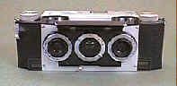
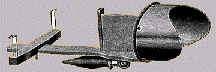
Kodak have also produce a number of stereo cameras, the last
of which, was introduced in the 1950s and called a Stereo
Realist. This camera could take two pictures simultaneously on
35mm film. A number of other manufactures made similar cameras
with negatives of the same size and format but these failed to
gain popularity.
 In the late 70s, two Americans, Jerry Nims and
Allan Lo, developed a new stereo system based on a new print
technology. The camera they developed called the NIMSLO takes
four images per picture. A special developing process combines
these images into one so that the resulting picture can be viewed
without the aid of any special equipment. The camera uses
standard 35mm film and produces 18 pictures from a 36-exposure
film. Despite very aggressive marketing, the system failed to
achieve its full potential in the photographic market place.
However, cameras from a number of manufacturers including single
use devices are still readily available although processing can
only be done in America at present.
In the late 70s, two Americans, Jerry Nims and
Allan Lo, developed a new stereo system based on a new print
technology. The camera they developed called the NIMSLO takes
four images per picture. A special developing process combines
these images into one so that the resulting picture can be viewed
without the aid of any special equipment. The camera uses
standard 35mm film and produces 18 pictures from a 36-exposure
film. Despite very aggressive marketing, the system failed to
achieve its full potential in the photographic market place.
However, cameras from a number of manufacturers including single
use devices are still readily available although processing can
only be done in America at present.
Dennis Gabor invented the ultimate stereoscopic photograph,
the hologram, in 1947 but it was not until Leith and Upatnieks
discovered a simplified process in 1961 that holograms were
manufactured commercially. Holograms give true three-dimensional
representations which allow the viewer to see the subject
correctly from different angles. Holograms are virtually
impossible to copy and are therefore used as security devices on
credit cards, software and designer labels.
To understand how the stereo technique works, an understanding
of human vision is required. The human eye is essentially a fully
automatic digital camera with a variable focus lens, variable
aperture and a surface for converting the light pattern into
electrical signals for the brain to interpret. The image from an
eye is essentially a 2-D picture i.e. we can see width and height
but no indication of depth. With 2-D images we can determine the
order of objects receding into the background from visual clues
like size and overlap but have no sense of how far apart they
are.
Humans are blessed with having two eyes however, both forward
facing but horizontally spaced by approximately 60mm. When
looking at an object, each eye will produce a slightly different
image, as it will be looking at a slightly different angle. The
human brain combines both these images into one to give a
perception of depth. This processing is so quick and seamless
that the perception is that we are looking through one big eye
rather than two.
 Figure 7 - Stereo Vision
Diagram
Figure 7 - Stereo Vision
Diagram
The brain can also determine depth and how far objects are
away from each other by the amount of difference between the two
images that it receives. The further the subject is from the eye,
the less will be the difference between the two images and
conversely the nearer the subject, the greater the difference.
Figure 7 gives a graphical example of how this works. The left
and right eyes see the sun in the same place as it is in the
distance. The tree being much closer is seen in slightly
different places.
The whole process is called stereo vision and it is derived
from the Greek word `stereos’ which means form or
solid i.e. having three dimensions. Stereoscopy is therefore the
science by which two photographs of the same object taken at
slightly different angles are viewed together, giving an
impression of depth and solidity as in ordinary human vision. It
follows that stereo photography is the art of taking two pictures
of the same subject from two slightly different viewpoints and
displaying them in such a way that each eye sees only one of the
images.
The distance between the two viewpoints is called the stereo
separation and this should be the same as the average
person’s eyes i.e. 63mm. Accuracy is not important, however
as the brain is able to compensate but too large a separation
will produce an unresolvable image. When taking stereo
photographs, the camera should ideally be pointing at the subject
and the background should be kept in the same place in both
images (see figure 7). The simplest way to ensure correct
horizontal and vertical alignment is to note the position of a
distinctive feature in the background of the first shot and
ensure that it is in the same position in the second. The ideal
stereo separation should produce a ¼" difference in
position of the subject between the two images. In order to
achieve this, the separation of the cameras must alter in
proportion with the distance of the subject from the camera i.e.
the nearer the subject, the smaller the separation and vice
versa. Human eyes are of course fixed and this explains why we
lose stereo vision of objects as they recede into the distance.
As the subject gets closer, human eyes lose the ability to focus
long before the relatively large stereo separation makes the
image unresolvable. In order to see a 3-D effect when shooting
landscapes, therefore, the stereo separation has to be large and
typically measured in feet while close up and macro photographs
require a separation of a fraction of an inch.
There are no hard and fast rules when operating at these
extremes and it is advisable to experiment to find the separation
that best suits the subject and the camera equipment being used.
None of the authors who provide practical guidance on stereo
photography agree on a general principle for example John
Hedgecoe recommends a separation of 1/50th of the
distance between the camera and the subject for distant objects
and a ¼ of the subject distance for close-ups while others
suggest 1/30th of the subject distance should be used.
Dennis Brown, however, uses a different technique based on the
principle that to get the best stereo separation, the foreground
or subject should be shifted by approximately ¼" (6mm) and
the background to remain in the same position. He calculated the
amount of shift required for different subject distances and
camera focal lengths and produced the following table. The
distances in the table are modified by two further rules that
increase the separation by a factor of 2 if the subject is
halfway to the background and 4 if it is near the background.
| Camera Shift (inch/foot) |
Camera Lens Focal Length (mm)
|
| |
28 |
35 |
50 |
70 |
105 |
135 |
210 |
300 |
| .75" |
1.5 |
2 |
3 |
4 |
6 |
8 |
12 |
18 |
| 1.5" |
3 |
4 |
6 |
8 |
12 |
16 |
25 |
35 |
| 3" |
6 |
8 |
11 |
16 |
25 |
32 |
50 |
70 |
| 6" |
12 |
16 |
23 |
32 |
50 |
64 |
100 |
140 |
| 1’ |
25 |
32 |
45 |
64 |
100 |
125 |
200 |
280 |
| 2’ |
50 |
64 |
90 |
125 |
200 |
250 |
400 |
550 |
| 4’ |
100 |
125 |
180 |
250 |
400 |
500 |
800 |
1.1m |
| 8’ |
200 |
250 |
360 |
500 |
800 |
1m |
1.6m |
2.2m |
| |
Subject Distance (feet/miles)
|
The principles behind stereo photography are simple enough
however the practicalities are a little more complex. The
technique can be split into two specific areas, namely the
capturing and the presenting of the image. Capturing the image on
film requires the photographer to take two pictures from slightly
different viewpoints. The traditional method for doing this is to
use a camera with two or more lenses, shutters, iris and film
planes, which takes two pictures at the same time. These cameras
were specially made and traditionally quite large and expensive.
"Miniaturisation" came in the 1950s with the Stereo
Realist (see figure 3) and its use of 35mm film rather than roll
film and a number of other manufacturers developed compatible
systems.
Some cameras, typically 35mm with standard 50mm lens, can be
fitted with a beam splitting device which produces two images on
a single frame. This device basically uses mirrors to bring the
two images side by side so they fit into one standard 35mm frame.
 Figure 8 - Beam Splitter
Diagram
Figure 8 - Beam Splitter
Diagram
Other single camera solutions include the Nimslo camera as
discussed earlier which records four images per shot on 35mm film
and a technique called Xography on large format cameras. Both
these techniques are used to produce lenticular prints which will
be discussed later.
The advantage of the single camera system is that it is simple
to use and can take pictures which include moving objects as all
the images are recorded at the same instant. The stereo
separation is, however, fixed (distance between the lenses) and
there are a limited number of lens focal length options
available.
An alternative method is to use two identical cameras, which
are fixed on to a bar at the correct separation distance. The bar
would typically be designed to have a sliding mount for at least
one of the cameras so that the stereo separation can be altered
simply and quickly. The same lens, aperture, shutter speed and
focus distance must be set on each camera before the shutters are
released simultaneously. While this is a potentially expensive
solution, it is probably the most versatile as it allows the
photographer full control over the film format, exposure, lens
system and stereo separation.
A very simple and cheap version of the twin camera set-up can
be made from two disposable cameras secured by tape on to an
"L" shaped aluminium extrusion. Disposable cameras have
a fixed focus, aperture and shutter speed and so the exposure
should be identical. Use the viewfinder of one of the cameras to
line up the shot and then press both shutter buttons
simultaneously.
The mounting bar used for the twin camera set up can also be
used with just one camera by moving the camera from one position
to the other. Using a bar with a slide makes this simpler, gives
accurate stereo separation and ensures that the camera is kept at
the same height and distance from the subject. This method is
very simple and requires a minimum of outlay. However, all stereo
photography using a single camera cannot be used where the
subject is moving as the time delay between shots will mean that
the subject will be in a totally different position or not even
in the frame when taking the second image.
The simplest but least accurate method is just to move the
camera by hand. If the camera is hand held then by shifting body
weight from left to right foot or vice versa will provide a
relatively accurate stereo separation equivalent to the distance
between the eyes (60mm). Alternatively, the camera can be mounted
on a tripod and the whole assembly moved. Great care must be
taken however when using these methods to ensure that the height
is kept the same and that the camera is pointing at the subject
(a point in the background of the picture should be used as a
reference and it should remain in the same position in each shot).
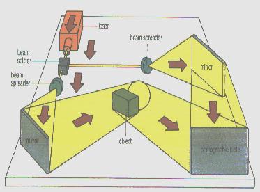 Figure 9 - Holography
Setup
Figure 9 - Holography
Setup
The creation of holograms requires lasers which are still very
specialised pieces of equipment and therefore not easily
available to most amateurs or professional photographers. The
laser produces a very pure and concentrated light source, which
is first split by being shone at a partially silvered mirror and
then widened using spatial filters. One of the beams called the
‘reference’ is shone directly at the film while the
other is reflected onto the film from the subject. The two light
sources create an interference pattern or ‘fringes’ on
the surface of the film which look like a series of craters or
smudges when looked at closely with normal light. Due to the
lighting and equipment requirements, this technique is generally
suited to still life although a number of photographers have used
it for portraiture e.g. the William Shakespeare hologram used on
credit cards.
In order to view the captured photographs, the images have to
be displayed in such a way that each of the viewer’s eyes
sees only one image. There are a number of techniques used to
achieve this and a number of examples of the main techniques have
been provided as an illustration in the Stereo Photography
Gallery in Appendix B.
 The stereoscope is the traditional method of
viewing stereo pictures or stereograms. The left and right images
aremounted on a card side by side (see figure 2). The card is
viewed in a "stereoscope" (figure 10) which is like
looking through a pair of binoculars. The design of these viewers
is such that the left eye cannot see the right eyes image and
vice versa. These viewers were very cheap and simple to make and
hence very popular. All stereoscopes work on the same principle
but as can be seen in figure 11, Victorian and Edwardian
ingenuity produced a wide range of viewers. Many of these viewers
are still available in antique shops at fairly modest prices and
can still be used with either original prints or with home made
stereograms. There is a resurgence of interest in old photographs
and many of the well known photographers material like Howlett
and Frith is getting harder to find and expensive. There is a
very great temptation to cut a stereogram in half and make twice
as much money and I feel that many great images will be lost to
future generations and that we will never be able to appreciate
theses images in the way they were originally intended
The stereoscope is the traditional method of
viewing stereo pictures or stereograms. The left and right images
aremounted on a card side by side (see figure 2). The card is
viewed in a "stereoscope" (figure 10) which is like
looking through a pair of binoculars. The design of these viewers
is such that the left eye cannot see the right eyes image and
vice versa. These viewers were very cheap and simple to make and
hence very popular. All stereoscopes work on the same principle
but as can be seen in figure 11, Victorian and Edwardian
ingenuity produced a wide range of viewers. Many of these viewers
are still available in antique shops at fairly modest prices and
can still be used with either original prints or with home made
stereograms. There is a resurgence of interest in old photographs
and many of the well known photographers material like Howlett
and Frith is getting harder to find and expensive. There is a
very great temptation to cut a stereogram in half and make twice
as much money and I feel that many great images will be lost to
future generations and that we will never be able to appreciate
theses images in the way they were originally intended
There are a number of modern versions of the stereoscope
available today for viewing pictures. The "View Magic"
is a viewer designed in America which requires the two images to
be mounted vertically rather than horizontally. The viewer uses
mirrors to align the images correctly so that they appear to be
horizontally mounted. Mounting the images in this way removes one
of the limitations on stereo photography i.e. the size of the
print. Human vision is designed to have a wide angle of view
horizontally i.e. letterbox format but traditional stereoscopic
photographs tend to be square. The reason for this is that the
traditional horizontal mounting of the images means the centre of
both images must be approximately 60mm apart i.e. the same as the
distance between the eyes. The images can therefore only be 60mm
wide and although height is not restricted in theory, most
viewers used a fixed mount for the composite image i.e. the
viewer could not be moved relative to the image being viewed
which restricts the viewing height. These restrictions do not
apply to the "View Magic" device as it is a hand held
viewer and can therefore be used with any width prints. The only
imitation is the height which can be a maximum of 4" as the
mirrors are set for this print height and cannot be adjusted.
‘Free Viewing’ is another technique for viewing
horizontally mounted images without the aid of a physical viewer
device. When Free Viewing, the eyes should not converge but look
parallel as if the image being looked at is in the distance. The
brain is fooled into thinking that it has two separate images and
creates a 3-D visualisation. The viewer will often be able to see
three pictures at this point i.e. the left image, the 3-D image
and the right image.
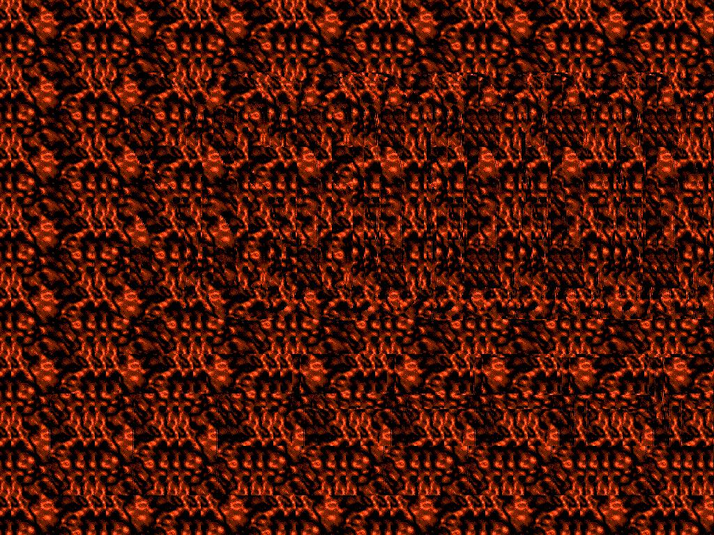 A recent development of the ‘Free
Viewing’ technique is the "Magic Eye" picture or
the "Single Image Random Dots Stereogram (SIRDS)" and
the "Single Image Stereogram (SIS)". These pictures are
created by computer and generally comprise of a simple picture
e.g. a fish hidden within a pattern of colours. The pattern can
either consist of seemingly random dots or a repeating vertical
pattern. "Magic Eye" pictures rely on the fact that the
brain depends on matching vertical edges to synchronise the left
and right images. The picture is made up of columns of patterns,
which vary slightly across the picture. The brain interprets the
columns as left and right pairs and the slight differences
between each column define the subject e.g. the fish. "Magic
Eye" pictures also use a number of different ‘Free
Viewing’ techniques which I have listed in Appendix A.
A recent development of the ‘Free
Viewing’ technique is the "Magic Eye" picture or
the "Single Image Random Dots Stereogram (SIRDS)" and
the "Single Image Stereogram (SIS)". These pictures are
created by computer and generally comprise of a simple picture
e.g. a fish hidden within a pattern of colours. The pattern can
either consist of seemingly random dots or a repeating vertical
pattern. "Magic Eye" pictures rely on the fact that the
brain depends on matching vertical edges to synchronise the left
and right images. The picture is made up of columns of patterns,
which vary slightly across the picture. The brain interprets the
columns as left and right pairs and the slight differences
between each column define the subject e.g. the fish. "Magic
Eye" pictures also use a number of different ‘Free
Viewing’ techniques which I have listed in Appendix A.
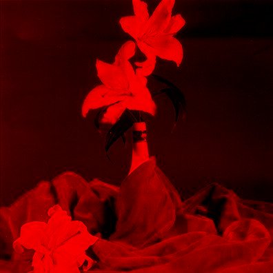
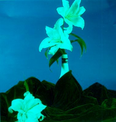
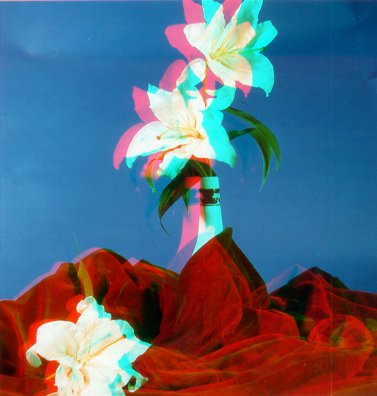
Like the "Magic Eye" pictures, the remaining
techniques for displaying 3D-Images will all use a single image,
which contains all the information, required to reconstruct the
full picture. The most common of these is the Anaglyph which
requires the viewer to wear glasses with red and green/cyan
lenses. The left image has the blue and green colour channels
removed to leave a purely red picture while the right image has
the red channel removed. The two images are superimposed into one
picture which produces a picture very like the original with a
red and cyan fringes around objects where the stereo separation
produces differences in the original images. The red and cyan
lenses in the glasses let the eyes separate the two superimposed
images into their individual components which the brain then
combines to form a 3D-image.
 |
+ |
 |
= |
 |
Left Eye Image
(Red Channel Only)
|
|
Right Eye Image
(Red Channel
Removed)
|
|
Anaglyph
(Left & Right
images overlaid)
|
Figure 12 - Creation of
an Anaglyph Lily
The filtration of the red channel can be done optically on an
enlarger, or on the camera with red and cyan filters fitted. The
simplest and quickest way however is to use a computer with
scanned images as the exact colour filtration can be controlled
and the degree of overlap of the two images adjusted to alter the
depth of the stereo effect. There are limitations to the process
however and great care must be taken to avoid the following
situations –
- High contrast areas – which will appear as ghosts or
shadows in the final image and can be very uncomfortable
for the viewer.
- Large red zones – No stereo effect will be seen with
areas of red as they will only appear in one of the
images. If using a computer, the red channel of the right
image can be edited and some blue or green added to the
problem areas, which will change the final colour but
give a stereo effect.
- Large Stereo separations create large colour fringes
which bias the overall colour of the picture. The image
displacement should be ¼" or less to avoid this
effect.
All the anaglyph images in Appendix B were created using
scanned images on a PC and as can be seen by the examples, the
process works on either black and white or colour images. The
anaglyph process is very simple and the viewer i.e. the glasses,
are very cheap to make. It is not surprising therefore that
anaglyphs have been used for a wide variety of applications
including 3D comics, page three girls, novelty items and movies.
 Lenticular prints
are an ingenious way of producing multiple or 3D images in one
picture without requiring a special viewing device. The final
picture comprises of a number of images that are printed as very
fine interlaced stripes. A special screen is laid over the top of
the picture allowing the viewer to see only the stripes which
correspond to one particular image at a time. The screen is
called a lenticular screen and it comprises of a series of very
fine lenses running in the same direction as the stripes. As the
viewing angle changes, a different image will be visible. If the
stripes are horizontal, then the final picture will contain a
series of images that can be seen by tilting the picture.
Vertical stripes are used for 3D pictures however as each eye
will have a different viewing angle and therefore be able to see
a different image. Horizontal lenticular prints are often used to
show motion sequences e.g. a horse running and are commonly used
in promotional novelties like the football card in Appendix B. If
a horizontal lenticular picture is turned through 90 degrees, a
confused and blurred image results as the two images seen by the
eyes do not match and cannot be resolved to make a 3D image. A 3D
Lenticular picture turned through 90 degrees allows the viewers
to see the individual images used to create effect.
Lenticular prints
are an ingenious way of producing multiple or 3D images in one
picture without requiring a special viewing device. The final
picture comprises of a number of images that are printed as very
fine interlaced stripes. A special screen is laid over the top of
the picture allowing the viewer to see only the stripes which
correspond to one particular image at a time. The screen is
called a lenticular screen and it comprises of a series of very
fine lenses running in the same direction as the stripes. As the
viewing angle changes, a different image will be visible. If the
stripes are horizontal, then the final picture will contain a
series of images that can be seen by tilting the picture.
Vertical stripes are used for 3D pictures however as each eye
will have a different viewing angle and therefore be able to see
a different image. Horizontal lenticular prints are often used to
show motion sequences e.g. a horse running and are commonly used
in promotional novelties like the football card in Appendix B. If
a horizontal lenticular picture is turned through 90 degrees, a
confused and blurred image results as the two images seen by the
eyes do not match and cannot be resolved to make a 3D image. A 3D
Lenticular picture turned through 90 degrees allows the viewers
to see the individual images used to create effect.
Xography, as mentioned earlier, is a technique used with large
format view cameras to produce stereo pictures. The camera is
fitted with a special elongated cylindrical lens and a horizontal
shutter, which travels from, left to right. A lenticular screen
in front of the filmplane ensures that the image is recorded as a
series of thin strips that represent the view from each eye. When
the negative is printed, a matching lenticular screen is placed
over the resulting picture so that the image can be viewed
correctly. A simpler way to make lenticular prints is to use a
NIMSLO or similar camera which takes three or more images per
picture. Processing for these cameras is only available in
America, however, there are a number of agents in the UK like the
"Widescreen Centre" who will handle the film.
Ultimately, the best 3D picture comes from the hologram as it
projects a complete representation of the original subject in
space. The original holograms required a laser to be shone
through the holograms surface in the reverse direction to that of
the original reference beam. The requirement of a laser and its
accurate positioning relative to the holograms surface limited
its usefulness however a new process of embossing has been
developed which gives a limited viewing angle but uses natural
light for viewing. The technique basically involves making a
hologram of the image projected by the original hologram. The
laser light used to make the hologram is filtered so that the
wavefronts of light are polarised in one direction and the
photographic plate has a special coating that forms an ultra thin
relief when developed which can be used as a die for embossing.
Once the master die has been created, copies of the hologram can
be made quickly and cheaply. The resulting holograms can be seen
in normal daylight however the subject will be seen from a fixed
vertical viewpoint while allowing a horizontal look around. This
type of hologram is often referred to as a rainbow hologram as a
rainbow effect is seen when the viewer’s eyes move
vertically.
The most important aspect of stereo photography is the human
brain and its ability to fuse the two images into a three
dimensional reality. Through my research and experiments with
stereo photography, I have discovered that a number of people,
including myself, do not see in 3D normally although most people
can see stereo photographs correctly. If no 3D effect can be seen
when looking at the pictures in appendix B then the following
research statistics may be of some comfort!
"Richards (1970; Experimental Brain Research 10,
380-388) did a survey among 150 MIT students and noticed that
"...about 4% of the students are unable to use the cue
offered by disparity, and another 10% have great difficulty and
incorrectly report the depth of a Julesz figure relative to
background." He further concludes that inability to use
stereopsis is an inherited defect and is related to
"three-pool"-hypothesis of binocular neurons."
There are many uses for stereo images apart from the obvious
artistic applications. I have already mentioned some in my essay
for example holograms used for copyright protection and there are
many more areas where a 3 dimensional view gives significant
advantages. Reconnaissance and cartography are two such areas
where these techniques are used to assess the lie and features of
the landscape. Trained military observers can spot subtle changes
in the landscape, tyre marks and a variety of other signs that
would indicate an enemy’s presence and position. Engineers
use holograms to detect minute changes in components when they
are subjected to stress. A hologram of the component for example
an aircraft tyres is made before and after ti is subjected to
some mechanical stress. The differences can be detected by
superimposing one hologram on another.
The theory behind stereo photography is simple, the creation
and delivery of the images can be complex. The basic technique
has a long history and its popularity has waxed and waned despite
numerous attempts to popularise it. There are a number of
societies around the world for this media, the oldest of which
was founded in 1893 in the UK. Several publications are also in
print although they tend to be published in America and not
easily found in Britain. There are many websites and newsgroups
on the Internet dedicated to this medium which display a variety
of stereo images and information. The popularity of "Magic
Eye" pictures and rainbow holograms in the mid 90s has
proved that interest in stereo photography still exists and has
helped to ensure the continued development of new technologies.
Credits, Copyright & Bibliography
Copyright
| Figure 1 |
- |
Perspective Frame, http://www.mmsweb.com/spectra/leonardo.htm
© Spectra Corp |
| Figure 2 |
- |
Isambard Kingdom Brunel, Johnstone T., Magic
3D 1995 © Sotheby’s |
| Figure 3 |
- |
Kodak Stereo Realist Camera, http://stereoscopy.com/cameras/index.html |
| Figure 4 |
- |
View-Master Viewer, http://www.members.aol.com/djadamson/20th3d/viewers.html
© Don Adamson |
| Figure 5 |
- |
View-Master Binocular Viewer, http://www.cinti.net:2000/~vmmasell/prod.htmp
© Sheldon Aronowitz |
| Figure 6 |
- |
NIMSLO 3D Camera, http://stereoscopy.com/cameras/index.html
|
| Figure 7 |
- |
Stereo Vision Diagram, modified from
original on http://stereoscopy.com/3d-info/index.html
P6 © Sylvain Roques & Bruno Pesce |
| Figure 8 |
- |
Beam Splitter Diagram, http://www.frii.com/~rkymtmem/3d.tutorial/beamsplit/beamsplitters.html
© Rocky Mountain Memories |
| Figure 9 |
- |
Holography Setup © The Hutchinson
Encyclopædia, Tenth edition (1992), Oxford, Helicon
Publishing, p. 503 |
| Figure 10 |
- |
Stereoscopic Viewer © http://cmpl.ucr.edu/collections/km/stereo/default.html |
| Figure 11 |
- |
SIS Pictire © Bob Manekshaw |
| Figure 12 |
- |
Anaglyph Lily picture © Bob Manekshaw |
| Figure 13 |
- |
Lenticular Screen © Hedgecoe, J. (1992)
The Photographers Handbook, 3rd
Edition, London, Ebury Press, p301 |
Bibliography & Websites
Brown, D. (1992) Practical Guide To Taking 3D Pictures, Harvard, Dimension Press |
|
Johnstone, T (1995) Magic 3D, London, Random House |
|
Hedgecoe, J. (1992) The Photographers Handbook, 3rd Edition, London, Ebury Press,
| |
http://www.bbc.co.uk/the_net/e2/history.html 17/04/98
http://www.stereoscopy.com (Provides links to a large number of 3D related sites
http://www.wscreen.demon.co.uk/ Widescreen Centre on line information service
http://www.comlab.ox.ac.uk/archive/3d.html Information on SIRDS
http://www.ccc.nottingham.ac.uk/~etzpc/sirds.html Information on SIRDS